Indentation creep of two monocrystalline ice cylinder. The top one has its c-axis parallel to the loading direction while the bottom one has its c-axis at 45° from the compression direction.
Post doctoral project
Lattice structures are good candidates for either aerospace parts (weight saving), or biomedical applications (osseointegration). They have very interesting properties, one of them being their large variety of strength-to-weight ratio depending on the chosen material, topology, density,... Additive manufacturing such as powder-bed-fusion methods seems the most appropriate type of process to produce them. In this work EBM was used to manufacture lattice structures and to find ways to integrate them in critical aircraft parts (in terms of fatigue resistance) in order to save some weight. However, great challenges are still to be overcome. One of them comes froms the process inherited defects that are quite detrimental for the fatigue lifes (especially notch-like defects). As machining is impossible for lattice structures, appropriate post-treatments were found, such as chemical etching and in a lesser extent ultrasonic shot-peening. Work on single struts was performed prior to this work, hence the focus on lattice structures. To reproduce the tensile-tensile fatigue tests realized on single struts, a stretching dominated unit-cell was used : the octet-truss.
In this work, a simple lattice structure was tested. It consists in an elongated structure made of 4 octet-trusses. This made easier X-ray tomography characterization on the whole lattice structure, as well as experimentally possible to follow which strut fails during fatigue tests. The idea was to optimize the fatigue life of this structure, but also to be able to predict it. To that end, post-treatments such as chemical etching and ultrasonic shot-peening were used, and a numerical method using Timoshenko beam elements was developed to predict the failure. This method used a damage accumulation law called the Miner's rule, and has the benefit to be easily tested with different sets of parameters (radius size distributions, S-N curve distributions).
The project was funded by the "Agence Nationale de la Recherche" (see the project web page here)
Densification from firn to ice is an essential phenomenon to understand for the interpretation of the climate record. A good knowledge of this mechanism is necessary for the precise dating of the air embedded in the ice. Pore closure (or close-off) is the stage at which air becomes entrapped in the ice. Typically, the close-off arises approximately 50 - 120m under the ice sheet surface. Because of gas flow in the firn column above close-off, the ice is older than the entrapped air. The difference between ice and gas is defined as Δage and may reach several millennia in certain sites. The precise determination of the Δage is mandatory to link temperature changes (recorded in the ice) and greenhouse gas concentrations (recorded in the gas phase). This issue may be addressed through the modelling of the firn densification processes that lead to pore-closure.
Firn densification consists of grain rearrangements, sintering and viscoplastic deformation. Although the viscoplastic behaviour of the ice crystal is strongly anisotropic, densification models do not take into account this anisotropy. Firn also bears some granular characteristics that may affect its densification. The interactions between pore closure and microstructural mechanisms in the firn are still misunderstood.
The aim of this PhD thesis is to incorporate both the granular aspect of firn and its anisotropy into an innovating approach of firn densification modelling. The mutual indentation of viscoplastic monocrystalline ice cylinders was experimentally carried out to propose a contact law that is based on indentation theory and that takes into account the preferential viscoplastic deformation on the basal plane. We have integrated this contact law into a DEM (Discrete Element Method) code for the prediction of firn densification.
3D X-ray micro-tomography was performed on polar firn at different stages of the densification (ρ= 0.55 - 0.88 g/cm3) and depths (23 - 130m). A thorough investigation of pore closure and of different morphological and physical parameters was achieved for the Dome C and the newly drilled Lock In polar sites. In addition to these ex situ analyses, in situ X-ray micro-mechanical experiments were carried out on firn extracted from Dome C in order to model its densification. Ex situ and in situ microstructural observations indicate significant differences that can be explained by the relatively large strain rates imposed to the firn during in situ tests. These large strain rates allow for a decoupling of the effects of diffusion kinetics and of viscoplastic deformation. Their relative weights on the morphology of pores and on their closure are discussed. To measure pore closure, we propose a connectivity index, which is the ratio of the largest pore volume over the total pore volume. We show that this index is better suited for X-ray tomography analysis than the classical closed porosity ratio to predict the close-off density.
As there should be no barriers in science, all presented work (in conferences) or publications are available for download at the bottom of the page.
As I defended my phD at the end of 2017, here is the final manuscript.
News
2020
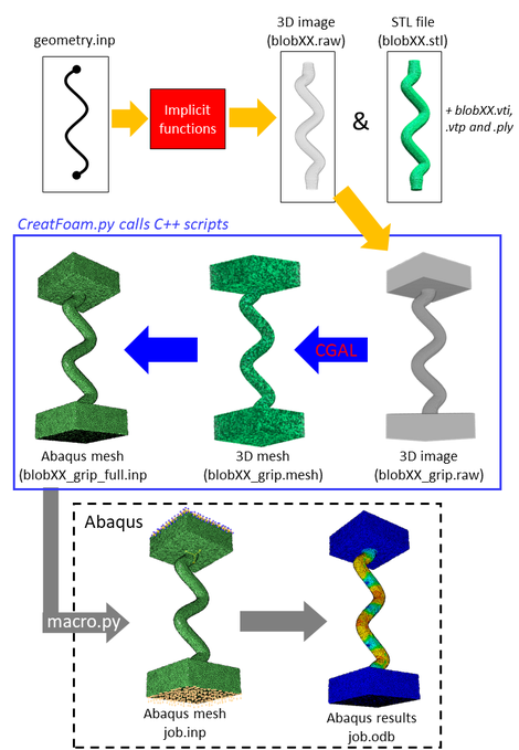
In this work, the code of Storm et al. [1] was used to create a volume mesh for lattice structures. In brief, the code of Storm uses implicit functions to mesh any structure. To summarize, if a strut is defined by two nodes connected by a beam, an implicit function is used to determine the surface of the strut according to various parameters (e.g. the desired radius). Many implicit functions are available, meaning that from one set of parameters (two connected nodes), one can create a cubic strut, an hyperboloid strut, a triangular strut and so on.
Once this surface is correctly described, the code uses CGAL [2] to perform a volumic mesh of a strut for external uses (typically in Abaqus Standard/Explicit [3]). This results in the creation of several output files representing the structures. These are represented in the right-side figure along with the different steps of the mesh generation.
My input in this work is the creation of quadratic tetrahedral elements from the linear ones obtained after CGAL (with one C++ script for speed). Then, the newly generated mesh can be automatically used in Abaqus for a dynamic non-linear analysis (here a tensile test on an elastoplastic material). The use of Abaqus was interested here because simulations can be run automatically using Python, with implicit or explicit integration schemes. Using quadratic linear elements was paramount here as bending is significant, which usually results in shear-locking when using linear elements.
References :
[1] Storm, J. et al. (2013). Geometrical modelling of foam structures using implicit functions. International Journal of Solids and Structures, 50(3-4), 548-555.
[2] CGAL : The Computational Geometry Algorithms Library
[3] Abaqus/CAE
For the right Figure, only one radius size distribution was used, and twenty draws of the same S-N curve distribution was used.
2019
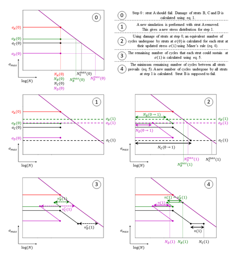
Using a radius size distribution of the lattice struts lead to a stress distribution within the lattice structure. In fact, the additive manufacturing process (here the EBM) leads to a gaussian distribution of the strut radius according to X-ray tomography analysis. When a stress is applied on the structure, each strut is submitted to a different stress. Looking at the S-N curves of single struts, one can predict which strut should fail first according to its stress (step 0 left Figure). When this strut is numerically removed (or broken experimentally), a stress re-distribution occurs (step 1 left Figure), meaning, the next strut that should fail could be one that is not the most loaded. As a result, a damage accumulation law called the Miner's rule was used to determine the correct order of broken struts. It uses the damage of struts over all re-distribution of stress considering the reference S-N curve of a single strut. (see details on step 3 to 4 in the left Figure).
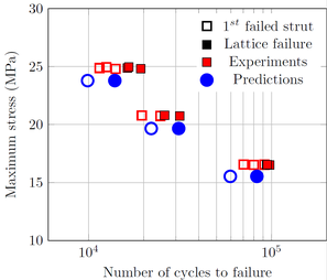
Thanks to this method, the progressive fatigue failure of lattice structures can be modelled and compared to experimental results (figure below). The gap between the first failed strut and the complete failure is correctly modelled and the fatigue life is also well-predicted (but requires a small tweak on the stress values...)
The figure on the left will be updated once the publication is accepted.
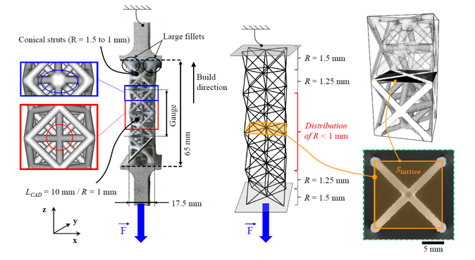
The tensile specimens consists in 4 superimposed octet-trusses : Octet-trusses near dense parts are made with fillets and conical struts so that failure is localized in a central gauge made of two octet-trussed lacking fillets. This structure can be modelled by Timoshenko beam elements with different radius size. The applied stress on the lattice structure is here defined by the applied force over the section shown in the figure below. Such model, using beam theory, enables to determine easily the stress distribution within the lattice structure.
2018
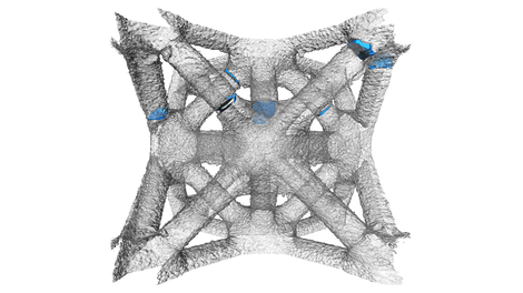
Lattice structures produced by EBM in Ti-6Al-4V consist in a stacking of several octet-trusses. Tensile specimen were made so that static and fatigue tests could be performed. During fatigue tests, failure of struts appears randomly in different octet-truss. Failure is also gradual enabling a grace period for which the specimen still holds. This is of primary interests in aerospace application where one part should be able to fulfill its function though being damaged. On the right hand side, a 3D tomographic reconstruction of a unit cell is shown, with blue aeras highlighting cracks where struts are completely broken.
November - April 2017
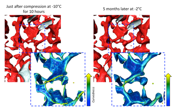
After a heat treatment of 5 months of a specimen that suffered an oedometric test, the same porosities are looked into (in the left hand side figure). They showed that the heat treatment does have an effect on the rounding of the porosities, as all the ridges are less curved than they were just after compression. More closed porosities were also found after the heat treatment, meaning that enabling diffusion to occur, does close the porosities (thanks to thermally activated mechanisms such as grain growth, sintering, ...).
July 2016
Firn core from the Lock In site is also characterized by X-ray.
June-July 2016
In situ mechanical tests were performed on firn that come from Dome C near the Concordia Station in Antarctica. The firn is taken at 80m deep in the ice core, corresponding to a density of roughly 0.78-0.79 g.cm-3 for an ice approximately 1880 years old. A displacement rate is imposed to the samples and X-ray scans are regularly performed to follow the evolution of the densification of these In Situ tests. Results are shown on the right side. First we can see that the closed porosities in red are appearing throughout the densification, and that closure appears by pinching of the porosity network. When comparing these with ex situ results, we observed that at a particular density, much less porosities were closed. An other difference is in terms of the porosities morphology. Ex Situ samples exhibited rounded morphologies, and smooth surface, while In Situ samples displays sharp morphologies, pointy dead-ends and acute shapes. These differences of shapes were quantifies by computing the curvatures. They are clearly explain from the duration of our experiment that lasted 8 hours, while densification occurred in 800 years in this range of densities for the ex situ samples.
March-May 2016
Firn cores of Dome C is analyzed by X-ray tomography giving Ex Situ results.
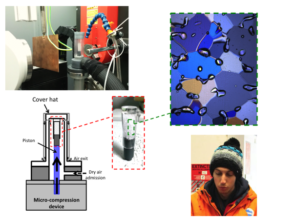
Development of a cold cell that adapts on a micro compression device is done in this period, and tested (and calibrated)
2015
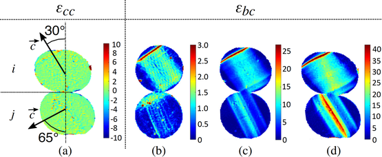
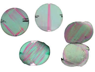
Mechanical tests on single crystals of ice. Deformations were tracked by polarized light and Digital Image Correlation. Strain maps were then compared to finite element results, taking into account the transverse isotropic law of ice. The aim of these experiments are to assess for a contact law that we implemented in the Discrete Element code.
Here is a glimpse of the work done. Figures on the left hand side and on the bottom can be found in : Burr, A., Noël, W., Trecourt, P., Bourcier, M., Gillet-Chaulet, F., Philip, A., Martin, C. L. (2017). The anisotropic contact response of viscoplastic monocrystalline ice particles. Acta Materialia. (can be downloaded below)